FIMMPROPA bi-directional optical propagation tool |
   |
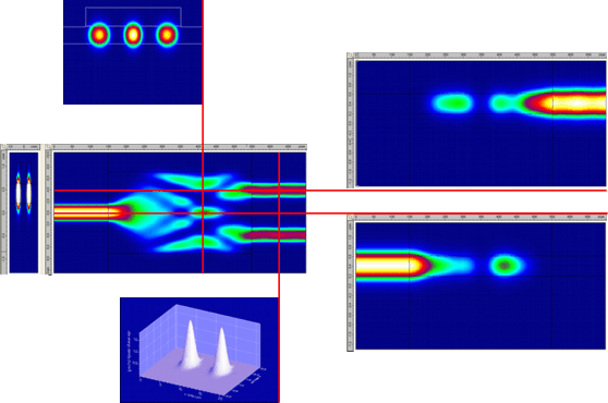
Field and Modal AnalysisField analysisFIMMPROP provides the user with flexible and exhaustive plotting tools allowing to plot any field section of the device. It is possible to plot any field component, the intensity of the field or the norm of the Poynting vector in any XY, XZ or YZ cross-section of the device and to export the associated data in a spreadsheet program.
It is also possible to plot fields profiles averaged along one direction, and to select the field propagating forward or backward.
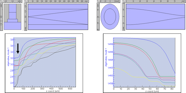
Modal analysisThe decomposition of the field in a set of eigenmodes reveals a lot about the physics of your device: transmission and coupling efficiency, losses due to radiation and optical leakage, beating effects, etc. FIMMPROP can plot the evolution of the power in each mode along the device, allowing you to follow the power in each mode of your waveguide and to study mode coupling for any kind of input. This is particularly useful to identify where problems occur in your design and how to improve it. FIMMPROP also allows you to plot the evolution of mode properties such as effective indices, mode losses, confinement factor etc. along your device. When designing a tapered structure, studying the evolution of effective indices is crucial to see how easily the taper can be made adiabatic, as can be seen in the picture below.
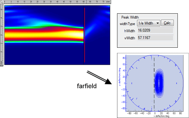
Farfield CalculatorYou can calculate the farfield of any mode or field profile using Photon Design's Farfield Calculator. The Farfield Calculator uses a fully vectorial plane-wave expansion algorithm to compute the farfield profile, which can be plotted on a spherical and a planar projection, as well as in the reciprocal K-space (useful for periodic structures). You can plot the profile and calculate the FWHM, 1/e and 1/e2 widths of your farfield. The Farfield Calculator includes an "aperture" feature which can compute how much light is incident on a given area, effectively measuring how much light would be received by a photodiode of finite size. You can even scan the position of the aperture to simulate the effect of a far-field scan in the lab.
Accuracy diagnosticsFIMMPROP is not just a black box! It allows you to find out how large an error you are making on the final results and where this error has built up in the device. This allows you to efficiently assess the accuracy of your simulation and to improve it efficiently by increasing accuracy where it is needed only, saving you calculation time.
|


