|
|
Your source of photonics CAD tools | |
|
| ||
PICWaveA photonic IC, laser diode and SOA simulator |
    |
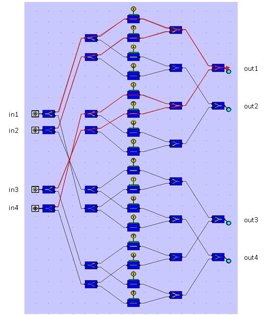
A 4x4 Optical Switch CircuitSimulation with PICWave softwarePICWave is able to efficiently model very large circuits. This example shows a 4x4 SOA switch circuit, shown below, containing 20000µm of waveguides, including sixteen 500µm-long SOAs. In this circuit, the SOAs are used to selectively absorb or transmit the input channels on the left (as well as providing amplification). The operation of the circuit is demonstrated by switching between the four input channels, in1..in4, and measuring the corresponding output at out1. The optical paths involved are highlighted in red in the figure below.
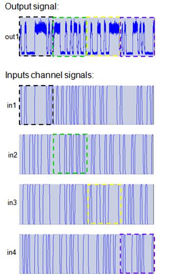
The switching was achieved by alternately switching on the first, second, fifth and sixth SOAs for 20ns, whilst leaving all the others switched off. The circuit was simulated over 80ns and took approximately 5 mins. to simulate. The resulting output signal is shown below, as compared with the four input channel NRZ data signals.
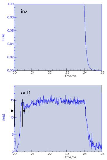
The switching between the four inputs at 20ns intervals can clearly be seen in the output signal. Like the 2R-Regenerator example, the output also contains noise added by the SOAs. The figure below shows a close up of the switching to the in2 signal at t = 20ns, which illustrates the effect of the carrier dynamics modelled by PICWave. Although the in2 signal is ON at 20ns, it takes a finite time for it to show up in the output, out1. This is because it takes time for the carrier density to reach the steady state when the SOA current is switched on/off. As can be seen, the switching time is of the order ~0.5ns, the carrier spontaneous lifetime.
|
 © 2023 Photon Design copyright all rights reserved |

 |