CrystalWaveA powerful photonic crystal simulator |
    |
Nonlinear FDTD: a Photonic Crystal CavitySimulation of nonlinear optics with CrystalWave nonlinear FDTD softwareThe performance of a nonlinear photonic crystal cavity has been investigated using CrystalWave’s nonlinear FDTD Engine and Band Structure Analyser. It has been observed that by increasing the input signal power the resonant frequency of the cavity changes, due to the Kerr nonlinear effect. CrystalWave's FDTD Engine supports chi2 and chi3 nonlinear materials (Pockels and Kerr nonlinear effects). These simulations are based on an optical switch design described in [1]. The results obtained with Crystalwave match the results of this publication with an excellent accuracy. Description of the structureNonlinear photonic crystals have remarkable properties for using in the all optical information processing, for example, the bistability of the nonlinear PCs have been utilized to design optical switches, transistors, logical gates, and optical memories. Here CrystalWave was used to simulate an optical switch based on a nonlinear photonic crystal cavity. The proposed structure shown below consists of a 15x15 2D square photonic crystal lattice of AlGaAs rods in air, in which a waveguide is created by introducing a linear defect. An additional point defect is introduced next to the waveguide, effectively creating a resonant micro-cavity. The AlGaAs rods have a radius of r = 0.2a, where a is the lattice constant, set to 1um.
Benefits of Crystalwave for this simulationCrystalWave presents many benefits allowing it to model this structure extremely quickly and accurately compared to other methods.
Modelling and simulation of the structure in CrystalWaveIn this case we are calculating the band diagram and identifying the photonic band gaps for the 2D photonic crystal lattice using the 2D Band Solver. As expected from the published results [1], the calculation revealed that the structure has a large photonic bandgap for transverse magnetic (TM) fields in the wavelength range 3.508425um - 2.387790um, allowing the cavity to support resonant modes.
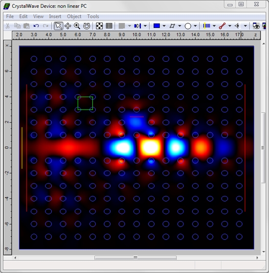
Using the "line defect" tool, which allows you to remove lines of lattice atoms in just a click, we created a waveguide and cavity in that photonic crystal by introducing a line defect and a point defect. The distance between the cavity and the waveguide was set to 2a. A first FDTD simulation was run in the linear case. A broad-band source with its central wavelength in the range of the photonic band gap was launched in the waveguide. Plotting a spectrum of the normalised transmitted flux versus wavelength allowed us to identify a single resonance at a wavelength of 2.6355um, with a Q factor of 160. At the resonance, light was strongly coupled to the cavity, resulting in a minimum power at the output. The strong coupling to the cavity can be seen below in a screenshot taken during the FDTD simulation.
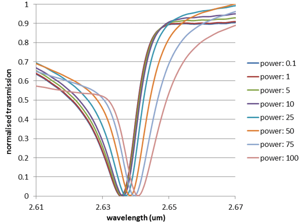
We then introduced the non-linear property of AlGaAs in the 2D FDTD simulation. We used a nonlinear-index coefficient of n2 = 1.5e17 m2/W, corresponding to the value given in [1] for a wavelength of 1550nm. CrystalWave allows users to set up and turn on and off the nonlinear modelling of individual materials very easily. We varied the input power between 0.001 to 1000 (arbitrary units) and observed that the resonance frequency started to shift due to the nonlinearity in the AlGaAs rods from an input power of 0.1. The normalised transmission spectra for different values of the input power are shown below; the shift can be very clearly identified. Beyond a power of 100, the cavity no longer supports a resonance.
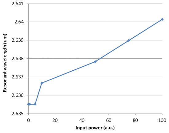
A plot of resonant wavelength versus input power is shown below, obtained from the nonlinear FDTD simulations. The shift in resonant wavelength due to the Kerr effect can be clearly observed.
Reference[1] N. Nozhat, A. Taher Rahmati and N. Granpayeh, "An All Optical Switch Based on Nonlinear Photonic Crystal Microcavities", PIERS Proceedings (2009)
|


