|
|
Your source of photonics CAD tools | |
|
| ||
FIMMPROPA bi-directional optical propagation tool |
   |
Propagation in Plasmonic WaveguidesSimulations with FIMMPROP softwareFIMMPROP can be used to model plasmonic waveguide components such as planar waveguides with metal layers or metal-coated optical fibers. A very efficient approach to model plasmonicsFIMMPROP can model such structures in the fraction of a time it would take to model them with an FDTD or FEM tool. If you were to model a planar waveguide with a thin buried metal layer in FDTD, you would need to use a grid spacing sufficiently small to render the thin layer and the spatial variations of the surface plasmons. In many cases this will mean a grid size of 1nm or less. Now imagine trying to use such a grid spacing over a device that is over 100um in length: this would be impossible without having to resort to the use of a computer cluster, and even then this would represent a large amount of computation time. FIMMPROP, as it is based on Eigenmode Expansion (EME), offers a much more efficient way to tackle such problems. The modes of each XY cross-section can be solved with one of FIMMWAVE's many complex mode solvers, such as the complex FDM Solver or the complex FEM Solver in Cartesian coordinates, or the complex FDM Fiber Solver in cylindrical coordinates. These solvers can use a very fine grid in the XY plane to model the thin metal layers. Once the modes are calculated, which should take no longer than a few minutes, FIMMPROP can model light propagation in a straight waveguide instantly, no matter how long it is.
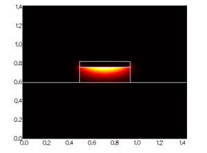
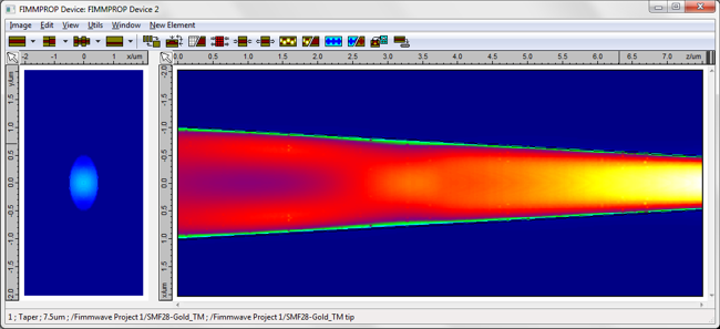
For z-varying structures, FIMMPROP's taper algorithm will determine how the structure needs to be discretised along the direction of propagation. The scale of the discretisation will be chosen based on how quickly the modes are varying, as opposed to how quickly the fields are varying (needed for FDTD), making FIMMPROP an extremely efficient approach for such structures. SNOM fiber probes: metal-coated tapered fibersThis can be applied to the case of of fiber probes used in near-field scanning optical microscopy (NSOM / SNOM): : these SNOM fibers are tapered and coated with metal at the tip to generate ultra-small spot sizes. We used FIMMPROP to simulate a glass fibre covered with a thin metal layer of thickness 22nm. Its core is tapered from a radius of 1um to 300nm on a length of 7.5um. Using the fully vectorial FDM Fiber Solver with a resolution of 0.2nm, the tapered fiber was simulated by FIMMPROP in 1 minute on a 4-core i7-2600 CPU. The simulation is particularly fast for this structure as FIMMPROP is able to take advantage of the cylindrical symmetry of this structure. For a wavelength of 1.55um we observed a 67% transmission for the fundamental mode. You can see the intensity profile below, with the cross-section on the left-hand side showing the field profile at the tip.
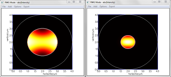
In addition to the scattering matrix (transmission, reflection) and the field profiles, FIMMPROP allows you to obtain more advanced information about the physics of your device by inspecting the mode properties along the structure. As the modes are already calculated by FIMMPROP whilst it generates the scattering matrix, this information is obtained at no further cost in calculation time. You can for instance see below the intensity profile of the fundamental HE11 mode at the input and output of the taper.
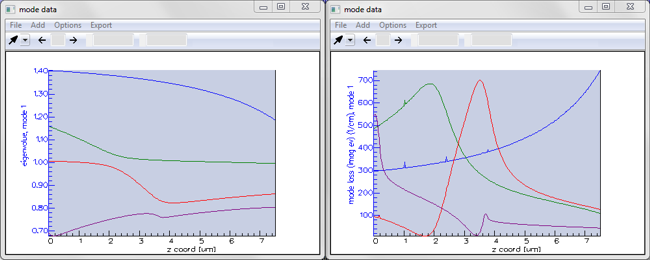
Here we have asked FIMMPROP to plot the evolution of the effective index and mode loss for the first four modes of the HE1n group. Please see here for more info.
|
 © 2023 Photon Design copyright all rights reserved |

 |