|
|
Your source of photonics CAD tools | |
|
| ||
FIMMPROPA bi-directional optical propagation tool |
   |
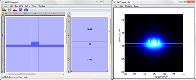
AR Coatings for Waveguide Facets3D simulations with FIMMPROP softwareA common approximation for the modelling of anti-reflection coatings is to consider that light propagates in the form of a plane wave along the z-axis. Although this 1D model is accurate for optical lenses, where the spatial variations in the XY plane are large compared with the wavelength, it is an approximate method when designing AR coatings for integrated optics and optical waveguides facets. FIMMPROP offers a rigorous 3D tool for the modelling of AR coatings which is fully vectorial and bi-directional. It allows you to optimise AR coatings so as to minimise the reflection associated with the actual physical mode of your waveguide. Using FIMMPROP's 3D model and our optimisation tool Kallistos we were able to improve an AR coating performance by 2dB compared with an optimisation performed with a 1D plane wave model. Description of the problemIn this example we are trying to minimise the reflection at the facet between a silicon rib waveguide facet and air in order to minimise back-reflections into a laser diode. We introduce a thin film coating that includes two layers: a first layer of silicon nitride Si3N4 and a second layer of silica SiO2. The thickness of both films is optimised using our optimisation tool Kallistos. The structure and the waveguide cross-section are shown below.
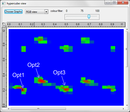
Limitations of the conventional 1D plane-wave modelA first optimisation is run using a 1D plane wave model: we consider each section to be uniform in the XY plane and we consider a single plane-wave in each section. The refractive index in the input section is set to the effective index of the fundamental mode for the waveguide, accounting for the wavelength dependence. We program Kallistos to calculate the total reflection at wavelengths of 1.50um, 1.55um and 1.60um and we ask it to minimise the sum of the three reflections. The results are shown below: along the horizontal axis is the thickness of the Si3N4 layer and along the vertical axis the thickness of the SiO2 layer. The red areas show the optima; in this case we find three optima of similar performance.
We calculate the reflection spectra for these three structures using the approximate 1D plane-wave model on the one hand, and FIMMPROP's rigorous 3D AR coating model on the other hand. The comparison of the results is shown in the plot below, which gives reflection in dB versus wavelength. The approximate results obtained with the 1D plane-wave model are plotted with dashed lines and the results obtained with the 3D FIMMPROP model are plotted with solid lines. Although the 1D plane-wave model would appear to find extremely low reflections, the 3D calculation reveals that in fact the approximate model under-estimates the reflection by up to 35dB! Overall it is clear that the 1D plane-wave model provides rather inaccurate results for this problem.
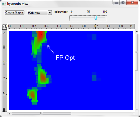
Optimisation using the rigorous 3D FIMMPROP modelA second optimisation was performed using the rigorous 3D FIMMPROP model, using the same parameter space and the same optimisation function. This optimisation took slightly longer: 58s per calculation point (20s per wavelength) as opposed to a fraction of a second for the 1D model. The results are shown below. In this case we get very different optimisation results, with one clear optimum.
The reflection spectrum for this new optimum is calculated with the rigorous FIMMPROP model. We compare in the plot below its performance with the performance of the optima found with the first optimisation. Performance comparison: improvement of 2dB!The new optimum is plotted in orange. You can see that the optimum calculated with FIMMPROP offers an improvement of at least 2dB over the entire range 1.45um to 1.65um, providing a performance which could not have been achieved when using a more approximate model.
Further simulationsFIMMPROP allows you to design AR coatings for a large variety of devices, including:
|
 © 2023 Photon Design copyright all rights reserved |

 |