|
|
Your source of photonics CAD tools | |
|
| ||
FIMMPROPA bi-directional optical propagation tool |
   |
A Lensed Optical Fiber (Fiber to Chip Coupler)Simulations with FIMMPROP softwareFIMMPROP was used to model a fiber-to-chip coupler based on a lensed fiber design. In this model a standard single mode fibre is tapered and lensed to focus light into a InGaAsP/InP ridge waveguide chip, whose position is adjusted for optimal transmission.
This example illustrates the following capabilities for FIMMPROP:
Description of the structureThe specifications of the fibre are given in the table below; it is a typical single-mode fibre with an operating wavelength of 1.545um.
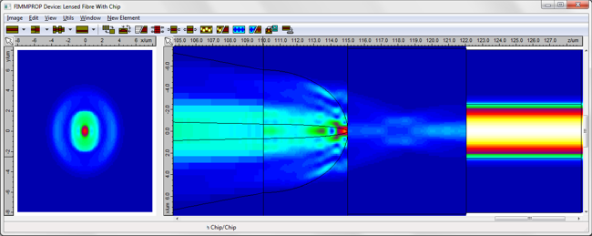
This fibre is pulled linearly over a length of 100um, where the cladding diameter reaches 10um and the core diameter is 1.33um; the fibre is then rounded off to create a hemispherical lens. This lens is used to focus the light over a small air gap (5-10um) into the InGaAsP/InP waveguide. The full structure is shown below. We combined FIMMPROP's fiber editor with the taper and lensed section design tools. Note how FIMMPROP is able to handle the variation in size along the structure. We used the semi-analytical and fully vectorial GFS Solver to solve the modes in the fiber sections, and the Cartesian FDM Solver in the planar waveguide section.
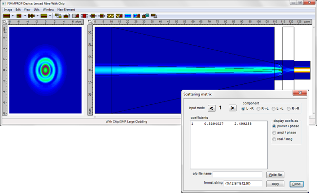
The propagation in the air gap between the tip of the lensed fiber and the chip is simulated using FIMMPROP's Free Space Joint, which propagates an analytical plane-wave expansion of the near field. The Free Space Joint's bidirectional algorithm can also model thin film filter and AR coatings; in this case you could also study the effect of introducing an AR coating on the chip facet. Simulation resultsFor this structure, FIMMPROP was able to calculate the scattering matrix and plot the intensity profile in ~half a minute on a 4-core i7-2600 PC. The intensity profile and the scattering matrix are shown below. At the end of the taper you can see the excitation of the high order modes of the fiber.
FIMMPROP was used to scan the evolution of transmission with distance between the tip of the lensed fiber and the chip facet, in order to optimise the focusing. The results are shown below - we find an optimal coupling of 34.0% for a gap of 7.0um. The oscillations correspond to constructive and destructive interference in the cavity formed by the two "facets".
The vertical alignment was optimised in a similar way. Similar simulationsNote that FIMMPROP can also model other types of fiber to chip couplers, including surface-emitting gratings, and various mode size converters (or spot size converters) such as grating-assisted mode size converters and inverted tapers.
|
 © 2023 Photon Design copyright all rights reserved |

 |