FIMMPROPA bi-directional optical propagation tool |
   |
A vertical fibre to waveguide grating couplerSimulated with FIMMPROP softwareFIMMPROP was used to model a vertical grating structure used to couple light from a planar silicon waveguide to an optical fibre. The design that was chosen is a popular fiber-to-chip coupler for a silicon waveguide (silicon on insulator, SOI) with a grating optimised for vertical fibre coupling, taken from a popular publication from Ghent University [1]. The results obtained with FIMMPROP match the results of the publication with an excellent accuracy. This structure can also be modelled with our FDTD/FETD tool OmniSim; you can find more details here.
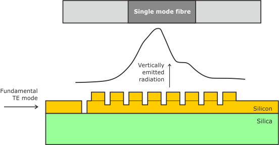
Description of the structure Description of the structureA 220nm-thick Si layer is grown on top of a 2um-thick SiO2 layer. An additional epitaxial silicon layer of thickness 150nm is grown locally on top in order to increase the directionality of the grating. A grating is created by etching equally-spaced slits in the epitaxial silicon layer, with an etch width of 160nm and an etch depth of 220nm. On the side of the excitation, an additional slit of same width and depth is etched on the 220nm silicon layer to minimise the reflection of the input beam. The distance "d" between the edge of the epitaxial silicon layer and the edge of the additional slit is varied. The coupler is designed to work optimally for a wavelength of 1550nm. The structure is represented below. A single mode fiber can be placed on top of the structure to couple light into the grating or to collect it; the simulation allows you to vary the properties of the fibre and its angle of inclination in the plane.
Benefits of FIMMPROP for this simulationFIMMPROP presents many benefits allowing it to model this structure extremely quickly and accurately compared to other methods. We used FIMMPROP's EME engine to model the grating.
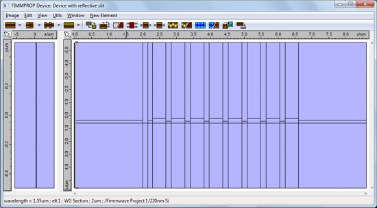
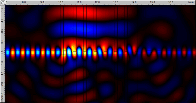
Modelling of the structure in FIMMPROPThis structure was designed and simulated in FIMMPROP in 2D. The structure and the final field profile at 1.55um are plotted below.
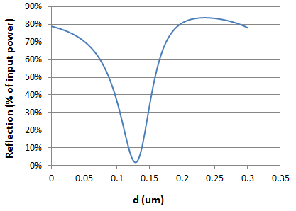
We used the fundamental TE mode for the excitation (field polarised in the plane of the slab, i.e. orthogonal to the 2D layout). PMLs were introduced at the top and bottom boundaries in order to absorb outgoing radiation. The scattering matrix for the structure was calculated in one and a half seconds. Cancelling out the reflection We started by studying the influence of the distance between the reflective slit and the edge of the epitaxial layer, in order to find the conditions required to fully cancel out the reflection. The variation of reflected power with distance is shown below for the central wavelength of 1.55um. Scanning the length of a section is extremely quick in FIMMPROP, which only recalculates what is needed: this scan of 50 steps was obtained in 5s. A reflection of 1.8% is achieved for d = 128.4nm, with an excellent agreement with Figure 4 in [1].
Exporting the radiation profile The radiating beam was obtained by exporting the field along the Z-axis at a small distance from the top of the waveguide into the air layer. The export was done for various distances in order to check that the results were independent of the choice of the position: this allows us to ensure that the evanescent tails of the guided modes in the grating have decayed to a negligible level.
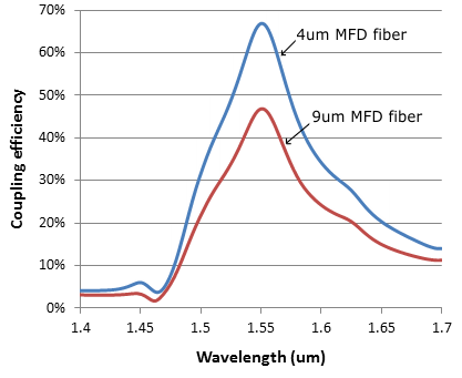
Calculating the coupling efficiency to the fibre Tools are provided with FIMMPROP to calculate the overlap between the radiation profile in air and the mode of the optical fibre, for various orientations of the fiber facet with respect to the grating surface. For the fibre mode we used Gaussian beams with mode field diameters of 4um and 9um. You can choose the orientation of the fiber in the XZ plane; in many grating designs the fiber is oriented with a small tilt angle. For a fiber facet parallel to the grating surface we identified the lateral position of the fibre that would provide us with optimal coupling at 1.55um. We then studied the evolution of the coupling efficiency with wavelength when the position of the fibre was fixed. The results of coupling efficiency versus wavelength are shown below. They match the published results with a very good accuracy; the optimal transmissions are in agreement with the Figure 5 in [1] with agreement to approximately 1%.
Extensive testing revealed an excellent convergence of the results when varying the PML width, the spatial resolution and the number of modes. Reference[1] G. Roelkens, D. Van Thourhout, R. Baets, "SOI grating structure for perfectly vertical fiber coupling", ECIO Proceedings 2007 (PDF)
|

