|
|
Your source of photonics CAD tools | |
|
| ||
OmniSimOmni-directional photonic simulations |
    |
A vertical fibre to waveguide grating couplerSimulated with OmniSim softwareNew! OmniSim now includes a Surface Grating Coupler Design Utility to automatically design and simulate surface grating couplers in 2D and 3D. OmniSim's FDTD and FETD engines were used to model a vertical grating structure used to couple light from a planar silicon waveguide to an optical fibre. The design that was chosen is a popular fiber-to-chip coupler for a silicon waveguide (silicon on insulator, SOI) with a grating optimised for vertical fibre coupling, taken from a popular publication from Ghent University [1]. The structure is modelled here in 2D but it can also be modelled in 3D with OmniSim. With OmniSim you can choose between the Finite-Difference Time-Domain and Finite-Element Time-Domain methods, and run the same simulation using two independent tools. This is very useful to check the accuracy of your calculations. The FDTD Engine allows you to run initial calculations quickly and with reasonable accuracy, and you can then use the FETD Engine once you want to obtain more precise results. This structure can also be modelled in 2D with our EingenMode Expansion tool FIMMPROP; you can find more details here.
Description of the structure Description of the structureA 220nm-thick Si layer is grown on top of a 2um-thick SiO2 layer. An additional epitaxial silicon layer of thickness 150nm is grown locally on top in order to increase the directionality of the grating. A grating is created by etching equally-spaced slits in the epitaxial silicon layer, with an etch width of 160nm and an etch depth of 220nm. On the side of the excitation, an additional slit of same width and depth is etched on the 220nm silicon layer to minimise the reflection of the input beam. The distance "d" between the edge of the epitaxial silicon layer and the edge of the additional slit is varied. The coupler is designed to work optimally for a wavelength of 1550nm. The structure is represented below. A single mode fiber can be placed on top of the structure to couple light into the grating or to collect it; the simulation allows you to vary the properties of the fibre and its angle of inclination in the plane.
Benefits of OmniSim for this simulationOmniSim presents many benefits allowing it to model this structure extremely quickly and accurately compared to other methods.
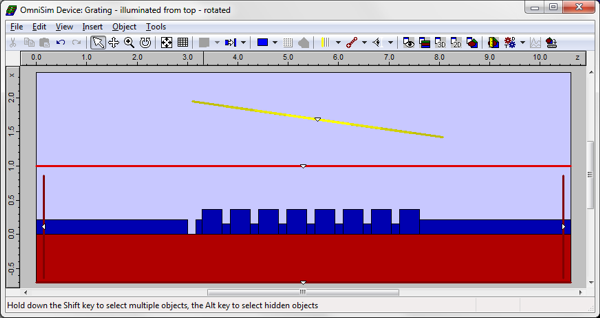
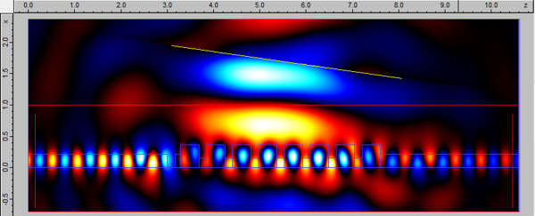
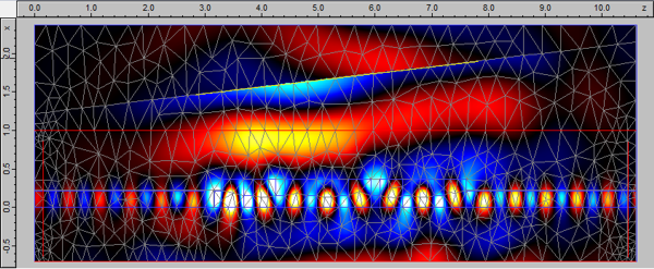
Modelling of the structure in OmniSimThis structure was designed and simulated in OmniSim's 2D layout. The structure is shown below, as well as a screenshot of the real-time fields plotted during the FDTD and FETD calculations with different orientations of the Gaussian excitor.
For this simulation we can inject light either:
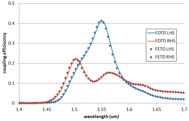
We used the TE polarisation for the excitation (field polarised in the plane of the slab, i.e. orthogonal to the 2D layout). PMLs were introduced at all boundaries in order to absorb outgoing light. Calculating coupling efficiency After sending a pulse of light through the excitor we can calculate the coupling efficiency. You can see in the plot below the coupling efficiency spectra to the left-hand side and right-hand side waveguides, obtained with the FDTD Engine (grid of 10nm) and the FETD Engine (resolution of 0.5um, 4th order elements) for a 5um wide Gaussian beam launched vertically (no tilt). The FDTD data is shown in solid lines, the FETD data in markers only. As you can see the two curves are very well matched.
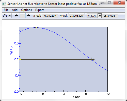
Effect of tilt and beam width We used the FDTD Scanner to study the effect of beam width and tilt angle on coupling efficiency. You can see below the results of coupling efficiency from the fiber to the waveguide mode at the left-hand side of the Device when varying the tilt angle.
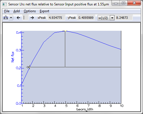
In the plot below you can see a scan showing the effect of beam width on coupling efficiency for the optimised tilt angle of -6 degrees; you can see that the optimal width is 5um.
Reference[1] G. Roelkens, D. Van Thourhout, R. Baets, "SOI grating structure for perfectly vertical fiber coupling", ECIO Proceedings 2007 (PDF)
|
 © 2023 Photon Design copyright all rights reserved |

 |