|
|
Your source of photonics CAD tools | |
|
| ||
OmniSimOmni-directional photonic simulations |
    |
Diffraction GratingSimulation with OmniSim FDTD and FETD softwareIn this example we use OmniSim's FDTD and FETD Engines to model a diffraction grating with an oblique incidence, and we compare the results with analytical data obtained from the grating equation.
Different approaches can be used to model such diffraction gratings:
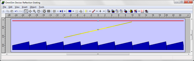
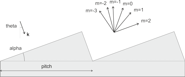
Incident beam of finite width: designing the gratingThe design is shown below. The dark blue region corresponds to the silver grating, and the pale blue region to air. We consider ten grating periods, the periodic structure being replicated automatically using OmniSim's sub-device feature. The structure was illuminated with a Gaussian beam (yellow line) and we measured with a sensor (red line) the light radiating from the grating. We used OmniSim's Farfield Calculator to measure the angles at which the radiation was reflected and diffracted.
The design settings are given in the table below.
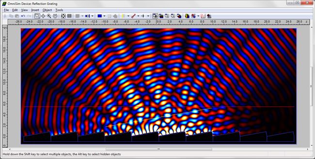
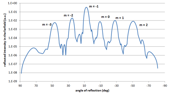
Incident beam of finite width: simulation results with FDTD and FETDYou can see below the farfield plot obtained after the FDTD calculation for light injected normal to the main grating facet, shown in logarithmic scale. The main peak corresponds to the diffraction of order m=-1 at an angle of 7.5 degrees from the normal to the grating, and the other peaks correspond to the different orders of diffraction. Similar results can be obtained from the FETD calculation. The convergence of the results was studied when varying the FDTD grid and the FETD mesh.
You can see in the table below the theoretical values for the diffraction angles for the different diffraction orders and the calculated values from the FDTD and FETD calculations; all three are in excellent agreement. Note that we use the convention of a positive angle for the direct reflection.
Note that these calculations cannot give you the amount of power coupled to each diffraction order with great precision as we are only considering a finite width of the grating and the peaks are broadened. You would be able to calculate the exact amount of power coupled to each diffraction order with the RCWA engine, which is ideal for such simulations. The FDTD Engine was able to provide initial results with a very good accuracy in 6 seconds on a computer with a 4-core 7i-2600 CPU; for that simulation we used a grid of 40nm. The FETD Engine was able to provide almost perfectly converged results in 1 minute 40 seconds. Modelling Echelle gratings and WDM devicesIf you are interested in modelling diffraction gratings for use in echelle gratings and WDM Devices, please have a look at Epipprop, our unique echelle grating model.
|
 © 2023 Photon Design copyright all rights reserved |

 |