|
Introduction
Features
‣
Layout
Editor
‣
FDTD Engine
‣
Cluster for FDTD
‣
Active FDTD
‣
FETD Engine
‣
FEFD Engine
‣
RCWA Engine
‣
Scripting / Optimisation
‣
GDSII Export
‣
Surface Grating Utility
Applications
Options
Publications
Download
‣
OmniSim brochure
‣
Nanophotonics brochure
Request evaluation
|
FDTD Simulation Software with OmniSim
Part of our state-of-the-art FDTD and FETD time-domain toolkit
The OmniSim and CrystalWave frameworks includes a highly efficient
FDTD (finite difference time domain) engine to simulate the propagation of light through your designs.
FDTD is ideal for modelling complex optical
structures including
ring resonators,
optical gratings,
photonic
crystals and
nano-photonics.
The FDTD engine is part of our
time-domain toolkit, which also includes
our unique FETD engine for accurate modelling of
plasmonics and
nano-antennae.
Overview of our FDTD engine
-
2D and 3D FDTD engine
-
Multi-core, multi-CPU FDTD calculations
and cluster support
-
Native 64-bit
version: virtually unlimited
memory
-
Advanced material
models
-
Unique sub-gridding tool
-
Active FDTD
algorithm for nano-lasers
-
Very fast speed optimised algorithm
-
More memory efficient than competing products,
featuring advanced memory reducing techniques (including running transform
as an alternative to Fourier transform)
-
Real-time field visualisation during the
calculations

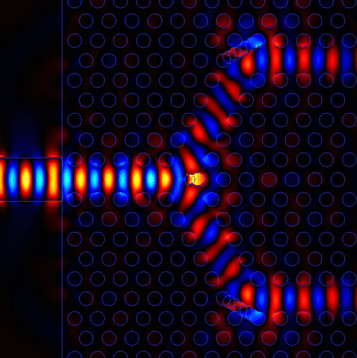
Finite Difference Time Domain (FDTD) simulation of a photonic crystal
Y-junction
FDTD Sub-Gridding
Photon Design's unique sub-gridding tool gives
you the ability to create 2x, 4x or greater increased resolution
in localised regions. 4x sub-gridding can accelerate a 3D simulation by
up to 64x. This is vital in plasmonics for modelling thin metals or small objects accurately, e.g. Mie scattering
on metal nanoparticles.

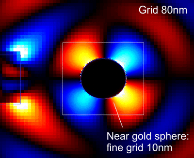
Resolution of the FDTD Engine increased locally with a sub-gridding
region
(the boundary of the sub-gridding region is shown with a white line)
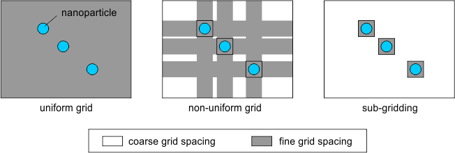
The main benefit of sub-gridding against uniform and
non-uniform grids is shown below. In this case the grid needs to be
refined around the surface of the nanoparticles. With a non-uniform
grid, large regions of the device still need to use a refined grid unnecessarily. The
use of sub-gridding regions allows to only increase the grid density
where needed, optimising calculation time.

Benefits of sub-gridding against uniform and non-uniform grids.
Innovative research work in partnership with Oxford University
allowed us to solve the problem of reflections usually associated
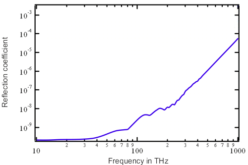
with sub-gridding in FDTD. The graph below shows the extremely low
reflection coefficient generated by our sub-gridding formulation for frequencies ranging from 10 to 1000 THz.

Anomalous reflection coefficient generated at the main-grid to sub-grid interface.
Ideally it would be zero. The graph shows an excellent low reflection
coefficient
of better than 1e-8 for a wide range of optical frequencies.
Materials
-
Supports transparent and lossy materials - users
can specify fixed refractive index and attenuation
-
Extensive material database with
standard dielectric
materials and metals
-
Dispersive materials models including Debye, Drude and Drude-Lorentz models
- and automatically generate model parameters
(fitting) from a supplied
dispersion spectrum.
-
Non-linear materials including chi2 and chi3
(see example
here)
-
Anisotropic refractive index - general symmetric tensor
-
Magnetic materials
-
Negative refractive index
materials
Boundary conditions
-
High performance PMLs on all six faces
-
Dispersive PMLs e.g. to match metals touching the boundaries
-
Metal (PEC), magnetic
(PMC) and periodic boundary conditions
Sources
-
Mode excitor: built-in mode
solver for excitation of waveguide mode
-
Dipole excitor: single dipole source or volume of incoherent dipoles (eg for modelling an LED).
-
Plane wave excitor,
Gaussian excitor
-
Beam excitor: arbitrary beam source,
supporting user-defined beam direction, focal point, polarisation and intensity profile.
-
Time envelopes: continuous
wave, sinusoidal pulse, sinusoidal rise or user-defined function
Sensors
-
Time-domain results and
frequency-domain results through Fourier analysis
-
Q-Factor calculator - calculate
Q-factor of resonance in typically 1/4 the time compared to using a
Fourier Transform
-
Farfield Calculator
-
Net flux, forward flux and backward flux sensors versus time, frequency or wavelength.
-
Measurement of mode power in
waveguide modes using built-in mode solver or imported mode profiles
(e.g. from FIMMWAVE)
-
Export spatial profiles for
flux, field components or intensity in any XZ, YZ or XY plane at a
chosen wavelength
-
Box sensors:
Additional features
-
Storing / Restoring results from an FDTD calculation
-
Batch manager
- submit multiple jobs to the engine at same time.
-
Run time monitoring of evolving fields: watch
the fields propagate in real time!
-
Video capture - generate a video of your FDTD
simulation using any codec installed in your PC.
Optional modules for the FDTD Engine
|


